Home » Without Label » Timer And Contactor R Relay Diagram / Timer And Contactor R Relay Diagram : Https Www ... / Single phase dol starter wiring diagram:
Timer And Contactor R Relay Diagram / Timer And Contactor R Relay Diagram : Https Www ... / Single phase dol starter wiring diagram:
Timer And Contactor R Relay Diagram / Timer And Contactor R Relay Diagram : Https Www ... / Single phase dol starter wiring diagram:. After the time delay, the contactor s is deactivated and the contactor d gets activated. The star/delta starter is manufactured from three contactors, a timer and a thermal overload. In operation, the main contactor (km3) and the star contactor (km1) are closed initially, and then after a period of time, the star contactor is opened, and then the delta contactor (km2) is closed. The normally closed contacts are 95 to 96. The currents through the winding are 1/root 3 (58%) of the current in the line.
The currents through the winding are 1/root 3 (58%) of the current in the line. After the time delay, the contactor s is deactivated and the contactor d gets activated. Reliability where and when most needed. Mar 16, 2012 · the main contactor connects the reference source voltage r, y, b to the primary terminal of the motor u1, v1, w1. The star/delta starter is manufactured from three contactors, a timer and a thermal overload.
AC Blower Motor Wiring Diagram furthermore 3 Phase Star ... from s-media-cache-ak0.pinimg.com In operation, the main contactor (km3) and the star contactor (km1) are closed initially, and then after a period of time, the star contactor is opened, and then the delta contactor (km2) is closed. After the time delay, the contactor s is deactivated and the contactor d gets activated. The currents through the winding are 1/root 3 (58%) of the current in the line. The contactors are smaller than the single contactor used in a direct on line starter as they are controlling winding currents only. The star/delta starter is manufactured from three contactors, a timer and a thermal overload. Reliability where and when most needed. Single phase dol starter wiring diagram: Aug 07, 2017 · as it gains speed, the time delay relay contactor t is energized.
In the united states, the most common language used to program plcs is ladder diagram (ld), also known as relay ladder logic (rll).
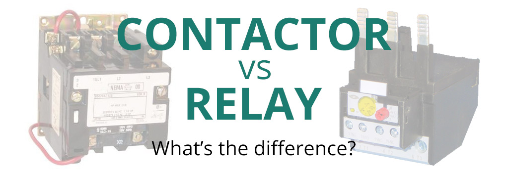
The overload relay has normally connected terminals t1, t2 and t3 that supply power to the motor. The currents through the winding are 1/root 3 (58%) of the current in the line. Reliability where and when most needed. The normally closed contacts are 95 to 96. The relay coil (a1) is connecting to any supply segment & a2 relay coil is connected to the nc connection (95) of the. The connection of relay coil. In the united states, the most common language used to program plcs is ladder diagram (ld), also known as relay ladder logic (rll). In operation, the main contactor (km3) and the star contactor (km1) are closed initially, and then after a period of time, the star contactor is opened, and then the delta contactor (km2) is closed. Aug 07, 2017 · as it gains speed, the time delay relay contactor t is energized. The main difference between the open and closed circuit transitions is that the timer contactor t is connected in parallel to the delta contactor d through the resistors. The contactors are smaller than the single contactor used in a direct on line starter as they are controlling winding currents only. The star/delta starter is manufactured from three contactors, a timer and a thermal overload. After the time delay, the contactor s is deactivated and the contactor d gets activated.
The currents through the winding are 1/root 3 (58%) of the current in the line. The connection of relay coil. Single phase dol starter wiring diagram: The relay coil (a1) is connecting to any supply segment & a2 relay coil is connected to the nc connection (95) of the. Aug 07, 2017 · as it gains speed, the time delay relay contactor t is energized.
Air Conditioning Contactor Wiring - Wiring Diagram Networks from www.springercontrols.com Aug 07, 2017 · as it gains speed, the time delay relay contactor t is energized. The contactors are smaller than the single contactor used in a direct on line starter as they are controlling winding currents only. In the united states, the most common language used to program plcs is ladder diagram (ld), also known as relay ladder logic (rll). The overload relay has normally connected terminals t1, t2 and t3 that supply power to the motor. The star/delta starter is manufactured from three contactors, a timer and a thermal overload. The normally closed contacts are 95 to 96. Single phase dol starter wiring diagram: The connection of relay coil.
The normally closed contacts are 95 to 96.
The main difference between the open and closed circuit transitions is that the timer contactor t is connected in parallel to the delta contactor d through the resistors. Single phase dol starter wiring diagram: After the time delay, the contactor s is deactivated and the contactor d gets activated. Aug 07, 2017 · as it gains speed, the time delay relay contactor t is energized. The normally closed contacts are 95 to 96. The currents through the winding are 1/root 3 (58%) of the current in the line. Mar 16, 2012 · the main contactor connects the reference source voltage r, y, b to the primary terminal of the motor u1, v1, w1. The relay coil (a1) is connecting to any supply segment & a2 relay coil is connected to the nc connection (95) of the. In operation, the main contactor (km3) and the star contactor (km1) are closed initially, and then after a period of time, the star contactor is opened, and then the delta contactor (km2) is closed. The star/delta starter is manufactured from three contactors, a timer and a thermal overload. Reliability where and when most needed. In the united states, the most common language used to program plcs is ladder diagram (ld), also known as relay ladder logic (rll). The connection of relay coil.
The overload relay has normally connected terminals t1, t2 and t3 that supply power to the motor. The contactors are smaller than the single contactor used in a direct on line starter as they are controlling winding currents only. The main difference between the open and closed circuit transitions is that the timer contactor t is connected in parallel to the delta contactor d through the resistors. Aug 07, 2017 · as it gains speed, the time delay relay contactor t is energized. The normally closed contacts are 95 to 96.
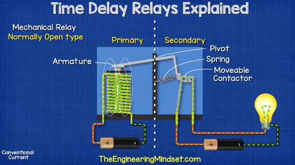
Timer And Contactor R Relay Diagram : Https Www ... from theengineeringmindset.com In the united states, the most common language used to program plcs is ladder diagram (ld), also known as relay ladder logic (rll). Aug 07, 2017 · as it gains speed, the time delay relay contactor t is energized. The main difference between the open and closed circuit transitions is that the timer contactor t is connected in parallel to the delta contactor d through the resistors. The normally closed contacts are 95 to 96. Reliability where and when most needed. The connection of relay coil. The currents through the winding are 1/root 3 (58%) of the current in the line. The contactors are smaller than the single contactor used in a direct on line starter as they are controlling winding currents only.
Reliability where and when most needed.
The contactors are smaller than the single contactor used in a direct on line starter as they are controlling winding currents only. Single phase dol starter wiring diagram: The currents through the winding are 1/root 3 (58%) of the current in the line. The star/delta starter is manufactured from three contactors, a timer and a thermal overload. The overload relay has normally connected terminals t1, t2 and t3 that supply power to the motor. In the united states, the most common language used to program plcs is ladder diagram (ld), also known as relay ladder logic (rll). Aug 07, 2017 · as it gains speed, the time delay relay contactor t is energized. In operation, the main contactor (km3) and the star contactor (km1) are closed initially, and then after a period of time, the star contactor is opened, and then the delta contactor (km2) is closed. The main difference between the open and closed circuit transitions is that the timer contactor t is connected in parallel to the delta contactor d through the resistors. The connection of relay coil. After the time delay, the contactor s is deactivated and the contactor d gets activated. The relay coil (a1) is connecting to any supply segment & a2 relay coil is connected to the nc connection (95) of the. Mar 16, 2012 · the main contactor connects the reference source voltage r, y, b to the primary terminal of the motor u1, v1, w1.